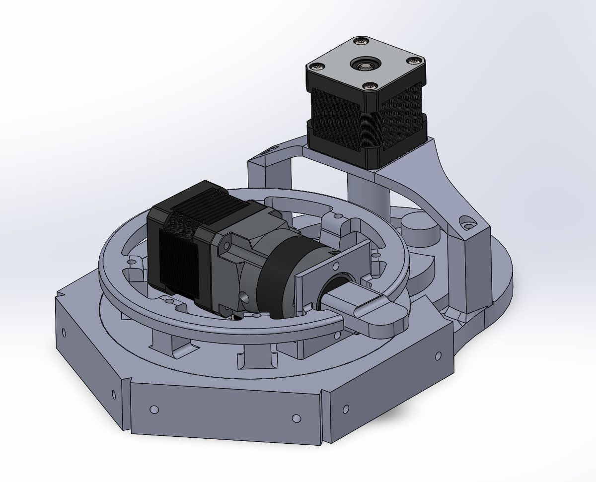
CAD
Peristaltic Pump + Geneva Drive
Mechanical design of a multi-position fluid-transfer system — peristaltic pumping, Geneva indexing, and NEMA stepper integration refined through iterative CAD.
Combined peristaltic fluid transfer with a Geneva indexing drive so continuous stepper rotation mapped to discrete pump stations.
This project involved the mechanical design and refinement of a multi-position fluid-transfer system built around a peristaltic pumping mechanism and Geneva indexing drive. The objective was to create a controlled method of transferring liquid between locations while using NEMA stepper motors and ensuring that the pumping mechanism could move between discrete positions rather than continuously rotating through them.
The system combined mechanical transmission, indexed motion, fluid handling, motor integration, and iterative CAD development. I was responsible for the mechanical design and subsequent refinement of the assembly, including the pump interface, rotating/indexing mechanism, structural components, and the geometry required to integrate the motor-driven system into a compact mechanical package.
Mechanical architecture
The core mechanical system consisted of a series of pump positions arranged around a rotating assembly. The peristaltic mechanism allowed the system to transfer fluid without requiring the tubing itself to be directly driven by an impeller or exposed to the drive mechanism.
A peristaltic pump operates by progressively compressing flexible tubing against a defined track or housing. As the rollers travel around the tubing, they create a moving zone of compression that displaces the fluid through the tube while maintaining hydraulic isolation between the fluid and the mechanical drive components.
This made the mechanism well suited for controlled fluid transfer because the liquid could remain contained entirely within the tubing while the actuation hardware operated externally.
The surrounding mechanical structure had to maintain consistent clearances between the tubing, rollers, rotating components, and stationary housing. Small variations in geometry could alter compression, introduce unnecessary mechanical resistance, or affect the consistency of the pumping action.
Assembly overview
Geneva drive
The most technically important mechanical decision in the project was the use of a Geneva drive for indexing.
The system used NEMA stepper motors, but continuous rotational output from the motor was not the motion profile I needed. Each pump position needed to be selected discretely, meaning the mechanism had to advance to one defined station and remain there before moving to the next.
A Geneva mechanism converts continuous rotary input into intermittent indexed output.
The driver wheel contains the drive geometry required to engage the Geneva wheel for a portion of each revolution. During engagement, the output wheel is advanced by a predetermined angular increment; once the driver exits the drive slot, the Geneva wheel enters its dwell period and remains mechanically constrained in its indexed position.
This gave the system a deterministic sequence:
- Continuous motor rotation
- Mechanical indexing
- Discrete pump position
- Dwell
- Next index
That was preferable to attempting to approximate indexed positioning entirely in software because the Geneva mechanism itself established the mechanical indexing geometry.
Indexed positioning
The number of Geneva slots directly determined the number of discrete positions available in the mechanism.
This allowed the rotating pump assembly to be divided into predetermined stations, with each index corresponding to a specific pump location. Rather than depending exclusively on encoder feedback or software timing to determine where the assembly stopped, the transmission physically defined the valid positions.
The resulting mechanism provided a form of mechanical state quantization: the output was constrained to a finite set of known angular states.
This was particularly useful when integrating the stepper motor because the motor could continuously rotate while the Geneva mechanism translated that continuous input into the discrete positional behavior required by the application.
Stepper motor integration
The system was designed around NEMA stepper motors, requiring the mechanical transmission to account for the characteristics of stepper-driven systems.
The motor interface had to provide sufficient torque to overcome the rotational inertia of the indexed assembly as well as the resistance introduced by the pumping mechanism and tubing compression.
I therefore had to consider:
- torque transmission
- shaft alignment
- radial loading
- mechanical backlash
- rotational inertia
- indexing geometry
- dwell stability
- structural rigidity
- mounting constraints
The motor and Geneva drive also had to remain mechanically synchronized. The engagement geometry had to provide enough clearance for reliable entry and disengagement while maintaining the positional accuracy required by the indexed output.
Mechanical refinement
A significant portion of my contribution was not simply creating an initial CAD model, but repeatedly improving the mechanism.
The design went through iterative changes to improve manufacturability, mechanical clearance, structural support, component alignment, and overall integration.
The CAD assembly was used to identify interference conditions between moving and stationary components before fabrication. Components such as brackets, motor mounts, structural supports, rotating plates, and retaining features were adjusted as the mechanical architecture evolved.
This process involved examining the assembly at both the component and system level.
A component could be dimensionally correct on its own while still producing interference once assembled, so the full mechanism had to be evaluated through its complete range of motion.
Pump mechanism
The peristaltic pumping system required controlled interaction between the tubing and the rotating compression elements.
The geometry of the pump housing and roller assembly determined how the tubing was constrained and how much compression was applied as the rollers passed over it.
This introduced a tradeoff between sufficient occlusion for reliable fluid displacement and excessive compression that could increase drag, wear the tubing, or increase motor load.
The mechanical design therefore had to balance:
- Tube compression
- Flow consistency
- Motor load
- Component wear
The rotating assembly also needed to remain concentric enough to maintain consistent interaction with the tubing throughout a full cycle.
Multi-position fluid transfer
The indexing system allowed the pump assembly to move between discrete fluid-transfer positions.
Rather than treating the pump as a single continuously operating mechanism, the Geneva drive effectively turned the assembly into an indexed selector.
The architecture could therefore be represented conceptually as:
- NEMA stepper
- Geneva transmission
- Indexed rotary platform
- Selected pumping position
- Peristaltic fluid transfer
This combination of continuous motor input and discrete mechanical output was the main reason for selecting the Geneva architecture.
The mechanical indexing system provided predictable station-to-station movement while the peristaltic mechanism handled the actual fluid displacement.
CAD and assembly design
A considerable amount of the work was performed at the assembly level in CAD.
I modeled the mechanism with attention to:
- mating interfaces
- mounting-hole patterns
- shaft locations
- concentric features
- fastener accessibility
- component clearances
- rotational envelopes
- material thickness
- manufacturability
- assembly sequence
The images of the design show a fairly dense mechanical assembly with multiple interacting subassemblies, meaning that interference analysis and spatial planning were important parts of the design process.
Several components were also designed around practical manufacturing constraints rather than purely theoretical geometry.
CAD detail
System-level engineering
The project required treating the pumping mechanism, transmission, motor, and frame as one integrated system.
For example, changing the position or geometry of the Geneva mechanism could affect the envelope of the rotating assembly, which could then affect pump placement, tubing routing, motor clearance, or structural support.
Likewise, changes to the pump geometry could alter the torque demand on the motor and therefore the mechanical requirements of the transmission.
This made the project a good example of mechanical co-design, where individual subsystems could not be optimized independently without considering their effect on the larger assembly.
Iterative engineering process
The design process followed the same general engineering cycle I use throughout my projects:
- Concept
- CAD
- Assembly
- Test
- Identify failure points
- Redesign
- Repeat
Rather than treating the first CAD model as the finished product, I used each iteration to identify mechanical shortcomings and improve the architecture.
The goal was not simply to make the mechanism function, but to make it function more reliably, with better mechanical integration and fewer opportunities for interference or misalignment.
What I learned
This project gave me practical experience with intermittent motion mechanisms, mechanical indexing, fluid-handling systems, and electromechanical integration.
The Geneva drive was particularly valuable because it demonstrated how a mechanical transmission can encode behavior that would otherwise have to be managed entirely through software.
Instead of asking the controller to continuously determine where the mechanism should stop, the transmission itself established the valid output states.
That distinction helped me understand the broader engineering principle of moving complexity into the physical architecture when a deterministic mechanical solution can provide greater repeatability.