Robotics
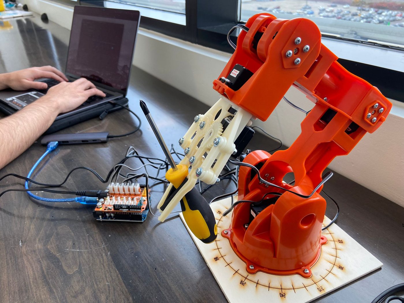
5-DOF Robotic Arm
A personal robotics project converting Cartesian coordinates into repeatable joint motion through kinematics, servo control, and calibration.
Achieved approximately ±8 mm positional repeatability after calibration and control tuning.
I designed, assembled, and programmed a 5-degree-of-freedom robotic arm as a personal robotics project, with the goal of taking user-defined Cartesian coordinates and converting them into repeatable joint positions. The project combined mechanical assembly, servo control, forward kinematics, calibration, and closed-loop control into a single system that could physically translate mathematical commands into motion.
The arm was controlled using an Arduino and programmed in C/C++, with each joint driven through servo motors. Rather than treating the arm as a collection of independently controlled motors, I approached it as a multi-joint kinematic system where the position of one joint directly affected the reachable workspace and final pose of the end effector.
Kinematic Model
One of the most significant parts of the project was implementing the arm’s kinematic model.
The objective was to allow a user to specify a target position in Cartesian space — specifically an (x, y, z) coordinate — and have the software determine the corresponding joint configuration required to reach it. This required understanding the geometric relationship between the arm’s link lengths, joint angles, and end-effector position.
At the time I built the project, I had not yet learned matrix mathematics or formal homogeneous transformation matrices. Instead of waiting until I had learned those methods, I derived the kinematics manually using trigonometry and geometric relationships between the joints.
I broke the arm into individual links and calculated the contribution of each joint to the final end-effector position. I used trigonometric relationships to determine the projected horizontal and vertical components of each link, then combined those components to determine the final Cartesian position.
This meant effectively constructing my own simplified forward-kinematics model without relying on matrix transformations.
For example, rather than representing the complete chain through a conventional Denavit–Hartenberg or homogeneous transformation framework, I explicitly calculated the positional contribution of each segment using joint angles and link dimensions. The resulting equations were then translated directly into embedded C/C++ code.
Although the implementation was more manual than a matrix-based approach, it forced me to understand what the kinematic equations were actually describing rather than treating the transformation process as a black box.
Forward Kinematics
The final software implemented forward kinematics to map a given joint configuration into an estimated end-effector position.
Each joint angle contributed to the cumulative pose of the arm, meaning that changing a proximal joint could affect the position of every downstream link. I therefore had to account for the compounded effect of multiple joint rotations rather than treating each axis independently.
The kinematic calculations were tied to the physical dimensions of the arm, including link lengths and joint offsets. Calibration was necessary to establish the relationship between commanded servo positions and the actual mechanical configuration of each joint.
The result was a software model that allowed the physical arm to be reasoned about in Cartesian coordinates rather than exclusively in raw servo angles.
Servo Control and Calibration
The arm used multiple servo-driven joints, each with its own mechanical range and positional characteristics.
I developed control logic to translate calculated joint angles into servo commands while accounting for the physical zero positions and operating ranges of the motors. Calibration was critical because the nominal servo angle did not necessarily correspond perfectly to the intended mechanical position once the servo was installed into the physical assembly.
I therefore established offsets and calibration values for the joints and tuned the system through repeated testing.
This created a pipeline that effectively looked like:
- Cartesian target
- Kinematic calculations
- Joint angles
- Calibrated servo commands
- Physical motion
PID and Motion Tuning
The project also incorporated PID-based control concepts to improve the behavior and repeatability of the arm.
Instead of relying entirely on abrupt positional commands, the system was tuned to achieve smoother and more controlled joint movement. PID parameters were adjusted against the physical response of the arm, accounting for the effects of mechanical load, inertia, servo behavior, and accumulated error.
The practical challenge was that the mathematical model and the physical robot were not identical. Mechanical tolerances, backlash, flex, servo positioning error, and assembly variation all introduced discrepancies between the expected and observed end-effector position.
Control tuning and calibration were therefore performed empirically.
Mechanical Integration
The software was developed around the physical constraints of the arm rather than independently of them.
The 5-DOF structure required careful consideration of joint placement, link geometry, servo mounting, mechanical range of motion, and end-effector positioning. The kinematic calculations were dependent on these dimensions, meaning that even a relatively small mechanical change could require corresponding changes to the mathematical model.
This made the project an integrated mechatronics problem rather than simply a programming exercise.
Results
After calibration and control tuning, the arm achieved approximately ±8 mm positional repeatability, allowing it to repeatedly reach commanded positions with reasonable consistency.
The project demonstrated my ability to move from a physical mechanism to a mathematical model and then from that model into embedded control software. It also gave me practical experience with the relationship between kinematics, servo control, calibration, and real-world mechanical error.
What I Took Away
One of the most valuable parts of this project was building the kinematic system before I had formally learned the mathematical tools that would normally be used to describe it.
I did not know matrix transformations at the time, so I solved the problem using direct geometric reasoning and trigonometric calculations. Later, learning about matrices made me realize that many of the calculations I had manually derived could be represented much more elegantly using transformation matrices.
That experience taught me something important about engineering: you do not always need to know the “proper” abstraction before you can solve a problem. Sometimes building the solution manually first gives you a much better understanding of what the abstraction is actually doing.